How to setup Alfa Laval Think Top Auto Valve?
How to setup Alfa Laval Think Top Auto Valve?
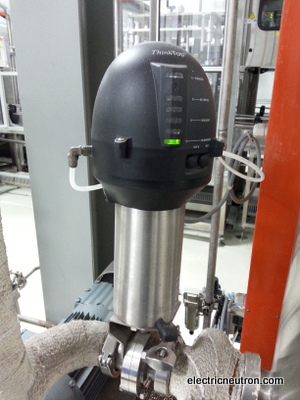
Alfa Laval Think Top is a control of sanitary valves that commonly used for hygiene or chemical manufactures.Think Top Basic offers a durable watertight design, a proven and inherently safe design and low total cost of ownership.
In my plant,all auto valves are using Alfa Laval Think Top that provide easy installation andconfiguration.This valve sensing and control head is optimized with fewer options and fewer digital connections. Think Top Basic is available in Digital, AS-Interface and ATEX versions.The ThinkTop Basic sensing and control unit is a uniform modular control head that consists of a proven no-touch, set-and-forget sensor system with light-emitting diodes (LEDs), solenoid valves and valve control sensor board for connection to any PLC (Programming Logic Controller) system.
For more detail please visit website: Alfa laval Think Top
This time I want shared some information how to setup or configure the ALfa Laval Think Top Basic before we can integrated with PLC function.This Auto Valve cannot function if we do not perform the configuration. Please follow procedure below and it’s easy to do.
Procedure of configuration for Alfa Laval Think Top

1. Ensure all electrical installation is correct as per manufacturer manual.
2. Ensure no fault occurred on the electrical connection such as short circuit, etc.
3. Ensure the DC voltage is presence on the control valve.
4. Initial actuator stem in on extend position.
5. Press “I” to enter setup and wait until the red LED blinking.
6. While the LED is still blinking, press “I” again to set-up. Now the red and green LED will turn on.
7. Then press “II” button to store the stem’s extend position and the red and orange LED will turn on.
8. Press the plunger ( III ) on the solenoid until the stem fully retract. While the plunger is still pressed, twist the plunger to lock the current (retract) position of the stem. No LED light status change.
9. Press “II” to store the stem’s retract stem position and red LED will blink.
10. Press “II” again to save and exit the set-up and simultaneously the orange LED will turn on.
11. Release the plunger ( III ) and the actuator stem ( IV ) will extend and resulting the green LED to turn on.
12. Now the valve controller is ready for operation.
For more detail information about wiring,installation and user manual please download thisAlfa Laval Think Top PDF
How to setup Alfa Laval Think Top Auto Valve?
 The ThinkTop® Basic is designed to ensure optimum valve control in conjunction with Alfa Laval sanitary valves and it is compatible with all major PLC systems (Programmable Logic Controller) with a digital PNP/NPN interface. It is for use in food, dairy and brewery installations and in biopharmaceutical applications. The ThinkTop® Basic fits all air operated valves from Alfa Laval.
Working Principle
The ThinkTop® Basic is a basic control head including sensor unit and solenoid valves to control processing valves. It is used to control and supervise pneumatic valves and is mounted on top of the valve. It receives signals from a PLC to control the solenoid valve and it sends the valve status feedback signals back to the PLC. To adapt the sensor unit to the specific valve, the users make a simple set-up by using local keys.
Sensor System
The sensor system is the well known and approved "No Touch" principle from the ThinkTop® platform without any mechanical sensor adjustments.
A magnet is mounted on the valve stem and the magnetic field (axial) is detected by build in sensor chips inside the sensor unit. The measuring angle from each chip is used in calculations to locate the current position of the valve stem. There can be programmed 2 PNP or 2 NPN feedback signals. The selection of PNP or NPN is done by a jumper on the sensor board itself. The LEDs are constantly indicating the status of the unit: Valve position, solenoids activated, set-up and local fault indication.
Feedback Signals
Output signals from the sensor unit to the connected digital interface (PLC).
Nominal voltage: . . . . . . . . . . . . . . .Same as connected to the ThinkTop® Basic.
Load current: . . . . . . . . . . . . . . . . . .50mA typical, 100mAmax.
Voltage drop: . . . . . . . . . . . . . . . . . .Typical X V at 50 mA.
Sensor Detection System
Sensor accuracy . . . . . . . . . . . . . . .+/- 0,1 mm.
Tolerance band: . . . . . . . . . . . . . . . .+/- 5 mm.
Distance tomagnet: . . . . . . . . . . . . .5 +/- 3 mm.
Stroke length: . . . . . . . . . . . . . . . . .0,1-80 mm.
PNP/NPN Polarity
PNP (sourcing) or NPN (sinking) function is selected by a jumper in terminals 9 and 10. Jumper present = PNP (standard). If changing to NPN remove the jumper and make a power recycle. A power recycle is always required when changing this function.
Solenoid Valves
0 to 3 solenoid valves in each unit possible.
Type: . . . . . . . . . . . . . . . . . . . . . . .3/2 or 5/2 port (only possible with one 5/2 port).
Air supply: . . . . . . . . . . . . . . . . . . . .300-900 kPa (3-9 bar).
Filtered air,max. particles of dirt: . . . . .0,01 mm.
Max. flow: . . . . . . . . . . . . . . . . . . . .180 l/min.
Throughput: . . . . . . . . . . . . . . . . . .¸ 2,5 mm.
Max. oil content: . . . . . . . . . . . . . . .1,0 ppm.
Max. water content: . . . . . . . . . . . . .0,0075 kg/kg air.
Manual hold override: . . . . . . . . . . . .Yes.
External air tube connection: . . . . . . . .¸ 6mmor¼". (Select when ordering).
Silencer/filter**): . . . . . . . . . . . . . . . .Connection possible via ¸ 6 mm or ¼".
Nominal voltage: . . . . . . . . . . . . . . .24 VDC.
Nominal power: . . . . . . . . . . . . . . . .1.0 W.
**): Filter recommended in tropical regions.
Technical Data
Materials
Plastic parts: . . . . . . . . . . . . . . . . . .Nylon PA 6, reinforced.
Steel parts: . . . . . . . . . . . . . . . . . . .Stainless steel ASI 304/316.
Air fitting: . . . . . . . . . . . . . . . . . . . .Special coated brass (FDA approved).
Seals: . . . . . . . . . . . . . . . . . . . . . .Nitrile (NBR).
Power Supply - DC
The ThinkTop® Basic is designed to be part of the PLC's Input/Output (I/O) system. It should be supplied from the same protected power supply as the other I/O devises. The I/O power supply should not be used for other kinds of loads. The unit is reverse polarity and short circuit protected. The power supply must meet the requirements of EN 61131-2.
Supply voltage: . . . . . . . . . . . . . . . .10-30 VDC.
Supply voltage nominal: . . . . . . . . . . .24 VDC ( +20%- 15%) - pr. EN 61131-2.
Max. ripple: . . . . . . . . . . . . . . . . . . .5% of nominal supply voltage.
Supply voltage absolutemax.: . . . . . . .30 VDC.
Supply voltage absolutemin.: . . . . . . .10 VDC.
Supply current): . . . . . . . . . . . . . . . .Max. 45mA (for sensor unit alone, excluding solenoids).
*): The initial current during power-on is higher. The actual shape of the current pulse depends on the power supply used. Typical values are 150 mA RMS during 13 ms (regulated PS) to 350 mA RMS during 8 ms (unregulated PS).
The fulfilling of the UL requirements in UL 508 requires that the unit is supplied by an isolating source complying with the requirements for class 2 power units (UL 1310) or class 2 and 3 transformers (UL1585).
Test conditions = One ThinkTop® Basic connected and 1 feedback active (on) and:


 1. De-energized (PLC input)
2. Energized (PLC input)
3. Activation of solenoid # 1 (PLC output)
4. Activation of solenoid # 2 (PLC output)
5. Activation of solenoid # 3 (PLC output)
6. Supply voltage sensor (+) 10-30 VDC
7. Supply voltage sensor (0) 0 V
8. Common supply solenoids
9. PNP/NPN jumper*)
10. PNP/NPN jumper*)
11. Solenoid common, internal connection
12. Solenoid # 1, internal connection
13. Solenoid # 2, internal connection
14. Solenoid # 3, internal connection
Fig. 1. Basic design, ThinkTop® Basic. *) Jumper present = PNP. If changing the function a power recycle is necessary.
The selection NPN/PNP is done by the jumper.

2. Light guide
3. O-ring
4. Base
5. Adapter
6. Shell
7. Terminals
8. Activator stem
9. Cable gland
10. Special X-ring
11. Air fitting
12. Solenoid valve (3/2 or 5/2)
13. Safety valve
14. Solenoid valve (3/2)
Fig. 2. Basic design, ThinkTop® Basic.
.

LED's
A. Energized (yellow).
B. Set-up/fault (red).
C. Solenoids (yellow)
D. De-energized (green)
Ordering
Please state the following when ordering:
- ThinkTop® Basic
- Digital 10-30 VDC PNP/NPN.
- Number of solenoids (0-3).
- Type of solenoids (3/2 or 5/2 port).
- Air connection ¸6mm or 1/4"
- Please state if for series 700 valves.
- For ThinkTop® Basic used on SSV-LS Stop valve size 63.5 - 101.6 mm/DN 65 - 100: Special indication pin must be used; 9612-6370-01.
- Unique SSV Long Stroke: Special indication pin must be used; 9613-1581-01.
Note! For further details, see also instruction manual ESE00225.
